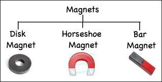
MAGNET
A magnet is a substance that attract other substances containing iron, nickel, cobalt etc.
MAGNETIC SUBSTANCES
The substances which are attracted by a magnet are known as magnetic substances. Eg: Nickel, cobalt, iron etc.
NON-MAGNETIC SUBSTANCES
The substances which are not attracted by a magnet are known as non-magnetic substances. Eg: wood, aluminium, paper etc.
PROPERTIES OF A MAGNET
1. A magnet always has two pole. i.e North pole and south pole.
2. When a magnet is suspended freely, it always rest in north-south direction.
3. In magnets, like poles repel each other and unlike pole attract each other.
4.Magnetic poles always exist in pairs. If a bar magnet is cut into two pieces then each piece will have its own north and south pole.
LAW OF MAGNETISM
The important law of magnetism are given below:
- Magnetic poles always exist in pairs. i.e North pole and south pole.
- Like poles always repel each other and unlike poles attract each other.
- Every magnet attract a small piece of magnetic substance towards it.
MAGNETIC FIELD
The region around a magnet where the force of attraction or repulsion can be detected by a magnetic substance is called magnetic field. It is a vector quantity. Its SI unit is Tesla and its smaller unit is Gauss.
1 Tesla = 104 Gauss
MAGNETIC FIELD LINES
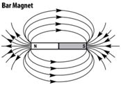
These are the imaginary lines around a magnet that represent the direction of magnetic field around it. Magnetic field around a magnet can be observed by sprinkling iron fillings around a magnet or by moving a magnetic compass around a magnet.
PROPERTIES OF MAGNETIC FIELD LINES
1.The magnetic field lines always originate at the north pole and merge at the south pole.
2. The magnetic field lines are closer at poles than other region.
3. The magnetic field lines never intersect each other.
Q: Why magnetic field lines never intersect each other?
Ans: As we know, magnetic field lines represent the direction of magnetic field at any point. If they intersect each other, then there will be two directions of magnetic field at the point of intersection which is impossible. Therefore, magnetic field lines never intersect each other.
UNIFORM AND NON UNIFORM MEGNAETIC FIELD
1. UNIFORM MAGNETIC FIELD: A magnetic field is said to be uniform if its magnitude and direction are same at every point in the magnetic field.
2. NON-UNIFORM MAGNETIC FIELD: A magnetic field is said to be non-uniform if its magnitude or direction are not same in the magnetic field.
MAGNETIC FIELD DUE TO A CURRENT CARRYING CONDUCTOR
If a magnetic compass is placed near a conductor(wire) carrying current, the needle of magnetic compass shows deflection. This shows that a conductor carrying current has a magnetic field around it.
1.MAGNETIC FIELD DUE TO A CURRENT THROUGH A STRAIGHT CONDUCTOR
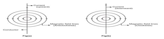
When a current is flowing through a straight conductor, then a magnetic field is generated around it. This magnetic field is in the form of concentric circles whose centre lies on the conductor (or wire).
This magnetic field can be observed by passing a current carrying straight conductor through a cardboard and sprinkling iron fillings on it.
MAXWELL’S RIGHT HAND THUMB RULE
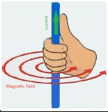
The direction of magnetic field around a conductor is given by Maxwell’s Right Hand thumb rule. It states that, “ If a conductor carrying current is held in right hand such that the thumb point in the direction of current, then the figure wrapped around the conductor shows the direction of magnetic field.
Q: What are the factors on which the strength of a magnetic field due to current carrying straight conductor depends?
Ans:
1. The strength of a magnetic field is directly proportional to the current flowing through a conductor.
i.e B α I
2. The strength of magnetic field is inversely proportional to the distance from the wire.
i.e B α 1/r
2. MAGNETIC FIELD DUE TO LOOP CONDUCTOR CARRYING CURRENT
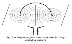
When current is passed through a circular conductor (loop), the magnetic field produced is in the form of concentric circles around the conductor. Towards the centre, the arcs of the circles become larger and appears as straight line.
Q:What are the factors on which the strength of magnetic field due to a current carrying loop conductor depends?
Ans: 1. The strength of magnetic field is directly proportional to the current flowing through the conductor.
- The strength of the magnetic field is directly proportional to the number of turns of wire in the coil.
- The strength of a magnetic field is inversely proportional to the radius of the loop conductor.
CLOCK FACE RULE
This rule states that when the current is flowing in anti-clockwise direction, then the face of the coil will behave like north pole. If the current is flowing in clockwise direction, then the faces of the coil behave like south pole.
ELECTROMAGNAT
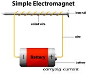
When a current is passed through a wire wound around an iron nail then it behave like a magnet. This magnet is called an electromagnet.
USES OF ELECTROMAGNET
1.An electromagnet is used in electric bells, electric motors, fans etc.
2.Electromagnets are used for sorting scrapped metals.
3.Gaint magnets are used to lift heavy machines and other heavy objects in industries
DIFFERENCES BETWEEN ELECTROMAGNET AND PERMANENT MAGNAT
ELECTROMAGNET | PERMANENT MAGNAT |
1. It is a temporary magnet. | 1. It is a permanent magnet. |
2. Strength of an electromagnet can be changed. | 2. Strength of a permanent magnet can not be changed. |
3. Polarity of an electromagnet can be changed. | 3. Polarity of a permanent magnet can not be changed. |
4. It provide a strong magnetic field. | 4. It provide weak magnetic field. |
FORCE ON A CONDUCTOR CARRYING CURRENT IN A MAGNETIC FIELD
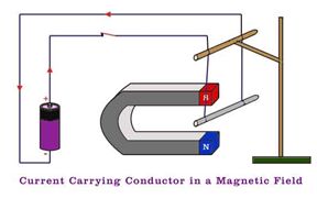
A.M ampere suggested that if a conductor carrying current produces a magnetic field and exert a force on a magnet then a magnet should also exerts a force on a current carrying conductor.
For example: If an aluminium rod is suspended horizontally by a wire between poles of a horse shoe magnet and current is passed through the wire, then the aluminium rod is get displaced. If the direction of current is reversed, then the direction of displacement is also reversed. The force exerted on a conductor is maximum if the conductor is perpendicular to the magnetic field.
NOTE: The force exerted on a conductor carrying current placed in a magnetic field can be calculated by the given formula.
F=IBlSinθ
Where I – Current flowing through the conductor
B- Strength of magnetic field
l – Length of conductor
θ- Angle between the conductor and direction of magnetic field.
Q: What are the factors on which force on a conductors carrying current in a magnetic field depends?
Ans: The force on a conductor carrying current in a magnetic field depends on the following factors
- Force on a conductor is directly proportional to the current flowing through the conductor.
- Force on a conductor is directly proportional to the strength of magnetic field.
- Force on a conductor is directly proportional to the length of the conductor.
- Force on a conductor is directly proportional to the sine of angle between the conductor and the direction of magnetic field.
FLEMING’S LEFT HAND RULE
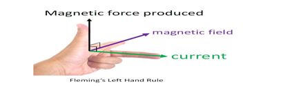
The direction of force on a conductor carrying current in magnetic field is given by Fleming’s left hand rule.
It states that, “If we hold the thumb, fore finger and middle finger of the left hand perpendicular to each other such that the fore finger points in the direction of magnetic field, the middle finger points in the direction of current then the thumb shows the direction of force on the conductor.
ELECTROMAGNETIC INDUCTION (Michael Faraday)
When a conductor moves with respect to a magnet or placed in a varying magnetic field then a current is induced in it. This phenomenon is known as electromagnetic induction and this current is called induced current.
EXPERIMENT-1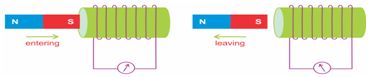 If a magnet is moved toward or away the coil connected to a Galvanometer, the galvanometer needle shows deflection. This shows that current is induced in it. This shows that motion of a magnet with respect to coil produces current.
EXPERIMENT-2
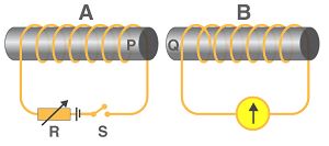
First of all take two coils of wire wound around a cylindrical paper roll. Connect the first coil to a battery and the other coil to a Galvanometer. If current is passed through the first coil then the galvanometer connected to the second coil shows deflection. If current is disconnected, the needle moves in opposite direction. This shows that current is induced due to change in magnetic field.
FLEMING’S RIGHT HAND RULE
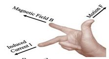
The direction of induced current is given by fleming’s right hand rule. It states that, “If the thumb , forefinger and middle finger of right hand are hold perpendicular to each other such that the thumb points in the direction of motion of conductor, forefinger points the direction of magnetic field then middle finger shows the direction of induced current”.
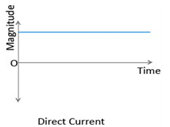
DIRECT AND ALTERNATING CURRENT 1.Direct current(DC): A current that always flows in one direction is called direct current. The current we get from a battery or a cell is a direct current.
 2.Alternating current(AC): A current that reverse its direction periodically is called alternating current. Most of the power station in our country produces alternating current.
Q: Give one advantage of Alternating current over Direct current.
Ans: One advantage of Alternating current over Direct current is that it can be transmitted over a long distance without much loss of energy.
Q: what is the frequency of electric current in our houses?
Ans: 50 hertz
DOMESTIC ELECTRIC CIRCUIT
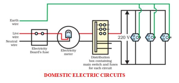
Electric power to homes is supplied with the help of two wires. One is live wire with red insulation and other is neutral with black insulation. The potential difference between the two wires is 220V. The earth wire with green insulation is connected to a metal plate kept under the ground.
In our homes two separate circuits are used. One is of 15A for appliances with high power like geyser , air conditioner etc. the other is of 5 A for appliances with low power like bulb, T.V, fans etc.
In domestic circuit, all the appliances are connected in parallel so that every the appliances gets equal voltage and also if one is switch off, the other will remain unaffected.
The appliances having metallic body like electric iron, refrigerator etc are connected to earth wire so that if a leakage of current then it passes to the earth and prevent us from electric shock.
ELECTRIC FUSE
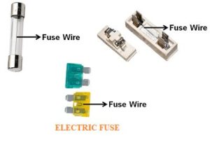
Electric fuse is a safety device used in electric circuit and appliance to protect the circuit and appliances from damage due to overloading and short circuit.
It is a wire having high resistance and low melting point. If excess current flows through the circuit, the wire melt and break the circuit. Fuse wire is made up of a metal or an alloy of metals like aluminium, copper, tin etc. A fuse wire is always connected in series wire with live wire.
ELECTRIC GENERATOR
An electric generator is a device that converts mechanical energy into electrical energy. An electric generator can produces AC as well as DC current.
PRINCIPAL OF ELECTRIC GENERATOR
An electric generator works on the principal of electromagnetic Induction according to which when a conductor carrying current moves in a magnetic field, then a current is induced in it.
CONSTRUCTION OF ELECTRIC GENERATOR
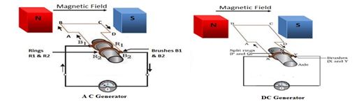
The different parts of an electric generator are as follows:
1.Field Magnet: A magnet is required to produce a magnetic field.
2.A Rectangular Coil: A rectangular coil ABCD is required to place between the poles of the magnet and in which current is induced.
3.Split rings or full rings: In AC generator full rings are connected to the ends of the coil and in DC generator split rings are connected to the ends of the coil. Spilt rings change the direction of current in coil after each half revolution. These split rings are also known as Commutator.
4.Brushes: A pair of brushes is required to connect the external device to rings.
WORKING OF AC GENERATOR
1.Initially we need to rotate the coil in clockwise direction so that the edge AB of the coil moves outward and the edge CD moves in inward direction, then according to fleming’s right hand rule, a current is induced in edge AB in upward direction and in edge CD in downward direction.
2. Now after half rotation when the edge CD moves in outward and edge AB moves inward then again according to fleming’s right hand rule, a current is induced in edge CD in upward direction and in edge AB in downward direction.
In this way the direction of current in the coil changes continuously after each half rotation and an AC current is generated by the generator.
WORKING OF DC GENERATOR
1.Initially we need to rotate the coil in clockwise direction so that the edge AB of the coil moves outward and the edge CD moves in inward direction, then according to fleming’s right hand rule, a current is induced in edge AB in upward direction and in edge CD in downward direction.
2. Now after half rotation when the edge CD moves in outward and edge AB moves inward then again according to fleming’s right hand rule, a current is induced in edge CD in upward direction and in edge AB in downward direction. In this way the direction of current in the coil changes continuously after each half rotation but due to split rings the direction of current also get reversed after each half revolution and we get a current flowing only in one direction and DC current is generated by generator.
Q: How can you increase emf(electro magnetic force) in a generator?
Ans: The emf in a generator can be increased –
- By increasing the number of turns of coil.
- By increasing the area of coil.
- By increasing the speed of rotation.
- By increasing the strength of magnetic field.
ELECTRIC MOTOR
Electric motor is a rotating device that converts electrical energy into mechanical energy.
PRINCIPAL OF ELECTRIC MOTOR
When a current carrying conductor is placed in a magnetic field then a force is exerted on the conductor. The direction of exerted force can be identified by using fleming’s left hand rule.
CONSTRUCTION OF AN ELECTRIC MOTOR
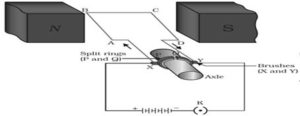
An electric motor consist of
1.Field Magnet: A magnet is required to produce a magnetic field.
2.A Rectangular Coil: A rectangular coil ABCD is required to place between the poles of the magnet through which current is passed.
3.Split rings: Split rings are required to change the direction of electric current after each half revolution.
4.Brushes: A pair of brushes is required to connect the split rings to battery.
5.Battery: A battery is required to produce an electric current in the coil.
WORKING OF AN ELECTRIC MOTOR
1.When the key is switched ON, the current flows in the coil through the brushes.
2.Initially current flows in side AB in upward direction and in CD in downward direction and the direction of magnetic field is from left to right.
3.Now according to fleming’s Left Hand Rule, a force on side AB acts in inward direction and on side CD in outward direction. Due to which the coil rotates in anti-clockwise direction.
4.After completion of half rotation, the split rings change the direction of current due to which the direction of current in side CD become upward and the direction of current in AB become downward.
5.Now again according to fleming’s Left Hand Rule . an inward force acts on side CD and an outward force acts on AB due to which coil again rotates in anti-clockwise direction. In this way, the coil continuously rotates in one direction.
Q: How can you convert an ordinary electric motor into commercial electric motor?
Ans: An ordinary electric motor can be converted into commercial electric motor
1.By using electromagnet in place of permanent magnet.
2.By increasing the number of turns in the coil.
3.By increasing the current in the coil.
4.By increasing the area of the coil.
Q: What do you understand by overloading and short circuit?
Ans: Overloading: Overloading is caused due to increases in voltage or if the live wire and neutral wire comes in contact or if too many appliances are connected to a single socket. It results in overheating of the wires and can cause damage to the circuit and appliances.
Short Circuit: Short circuit is caused when live wire and neutral wire come in contact and the current suddenly increases in the circuit.