ELECTRIC CHARGE
Excess or deficiency of electrons on a body is known as electric charge.
1. A body is said to be positively charged, if it losses electrons.
2. A body is said to be negatively charged, if it gains electrons.
The S.I unit of charge is coulomb (C)
QUANTIZATION OF CHARGE
The total charge acquires by a body is an integral multiple of charge on one electron. This principle is known as Quantization of charge.
If a body gains or losses n electrons and the charge on a single electron is -1.6 X 10⁻¹⁹ C, then
Total charge on body=ne ( where e= -1.6X 10⁻¹⁹ C)
PROPERTIES OF ELECTRIC CHARGE
The properties of electric charge are as follows
- Like charges repel each other.
- Unlike charge attract each other.
- It is a scalar quantities.
- It can be conserved.
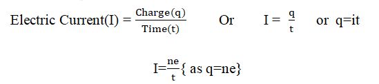
ELECTRIC CURRENT :The rate of flow of electric charge is known as electric current. It is denoted by I and its S.I unit is Ampere(A).
Note: Andre Marie Ampere gave the unit of current as ampere.
1 AMPERE- We know that I=q/t if q=1C and t=1sec then
I=1/1 = 1 Ampere
If 1cuolomb charge flows through a conductor in 1 sec. Then the electric current flowing through it is said to be 1 Ampere.
ELECTRIC POTENTIAL
Electric potential is defined as the work done to carry unit positive charge from infinity to an electric field.
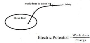
The S.I unit of electric potential is Volt(V).
ELECTRIC POTENTIAL DIFFERENCE
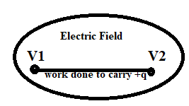
Electric potential difference is defined as the work done to carry unit positive charge from one point to another point in an electric field. The SI unit of electric potential difference is Volt(V). It is a scalar quantity.
Lets W be the work done to carry unit positive charge (q) from a point A to B. Then, the potential difference between A and B can be given as
∆V= VB-VA= W/q
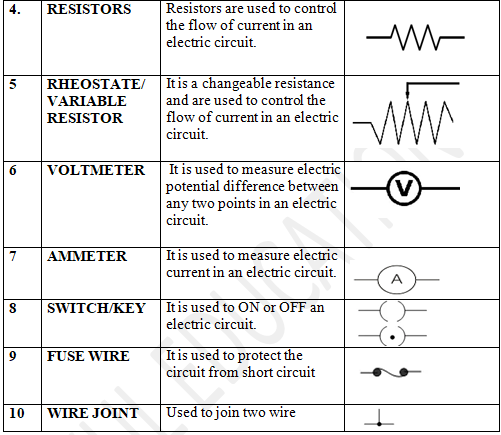
VOLTMETER
Voltmeter is a device used to measure electric potential difference between any two point in an electric circuit . It is always connected in parallel
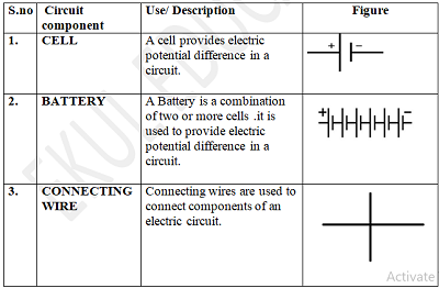
ELECTRIC CIRCUIT
Electric circuit is a closed and continuous path through which electric current flows. It consist of a cell, bulb, switch, voltmeter, ammeter , resistors etc.
ELECTRIC CIRCUIT
Electric circuit is a closed and continuous path through which electric current flows. It consist of a cell, bulb, switch, voltmeter, ammeter , resistors etc.
Closed Circuit | Open Circuit |
1. In closed circuit current flows | 1. In open circuit current dose not flow |
2. In closed circuit potential difference is established | 2. In open circuit potential difference does not established |
3. It is represented by symbol | 3. It is represented by symbol |
OHM’S LAW
Ohm’s law gives a relationship between the potential difference across a conductor and the current flowing through it.
Ohm’s law states that, ”At a particular temperature, the current flowing through a conductor is directly proportional to the potential difference between its ends.”
If current I flows through a conductor having a potential difference V across its ends then,
According to ohm’s law,
Potential difference α Current
V α I
V=RI
=> V=IR {Where R is proportionality constant and is known as the resistance of the conductor}
VERIFICATION OF OHM’S LAW
Ohm’s law can be verified with the help of the given activity
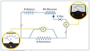
1. First of all setup a circuit as shown in figure.
2.Use one cell and note the current(I) in ammeter and potential difference(V) across the nicrome wire AB in voltmeter .
3. Repeat this process by using two cells , three cells and four cells and note the readings in ammeter and voltmeter.
4. Now plot a graph between the current(I) and potential difference across the wire.
Since, the graph between the Current(I) and potential difference (V) is a straight line. This shows that the current flowing through a conductor is directly proportional to the potential difference across its ends.
RESISTANCE
Resistance is the property of a conductor to resist the flow of current through it.
According to Ohm’s law
R= V/I
The SI unit of resistance is Ohm(Ω)
FACTORS ON WHICH THE RESISTANCE OF A CONDUCTOR DEPENDS
The resistance of a conductor depends on the following factors
- LENGTH OF THE CONDUCTOR
èResistance of a conductor is directly proportional to its length i.e R α l
2.AREA OF CROSS SECTION
èResistance of a conductor is directly proportional to its cross section area. i.e R α 1/A
On combining above two results,
R α l/A
![]()
Where (rho) is a proportionality constant and known as the resistivity of the material of the conductor.
RESISTIVITY
We know that R= ∫l/A ==> ∫= RA/l
If A= 1 m2 and l = 1 m
Then, ∫=R x 1 /1
∫=R
Resistivity of a material can be defined as the resistance of the material of Unit length(1 m) and unit Area(1 m2) of cross section. Its SI unit is Ω-m.
Note: 1. Conductor like metals and alloys have low resistivity (from 10-8Ω-m to 10-6Ω-m)
2.Insulator like rubber, glass etc have very high resistivity (from 1012Ω-m to 1017Ω-m )
Note:2. Resistivity dose no depend on the length and thickness of the conductor, it depends on the nature of the material of the conductor.
RESISTANCE OF A SYSTEM OF RESISTOR
In order to achieve desired resistance two or more resistors are combined in different ways. There are two different ways to combine resistance.
1.Series Combination of resistance
2.Parallel Combination of resistance
1.SERIES COMBINATION OF RESISTANCE
When two or more resistors are connected end to end, then they are said to be in series.
If three resistors R1,R2 and R3 are connected in series and potential difference across them are V1,V2 and V3
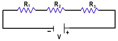
As we know, in series potential difference is divided but current remain same
Therefore,
V=V1 + V2 + V3
IR=IR1 + IR2 + IR3
R=I(R1 + R2 + R3)
R= R1 + R2 + R3
Thus , the equivalent resistance in series combination is equal to the sum of the individual resistance of resistors.
DISADVANTAGES OF SERIES COMBINATION
1. If any of the component fails to work then complete circuit will break.
2. We cannot connect two devices in series which needs different current to operate.
3. In series combination overall resistance of the circuit increases.
ADVANTAGES OF SERIES COMBINATION
1. In series combination less wire is required.
2. We can add more power devices like batteries or cells in order to increase voltage.
2.PARALLEL COMBINATION OF RESISTORS
When two or more resistors are connected simultaneously across two points, then they are said to be in parallel combination.
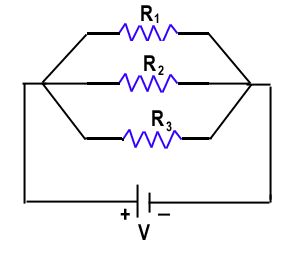
If three resistors R1, R2 and R3 are connected in parallel combination across A and B.
As we know, In parallel combination, current is divided but potential difference remain same. Therefore,
I=I1 + I2+ I3
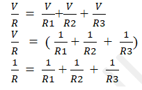
Thus , the reciprocal of the equivalent resistance is equal to the sum of reciprocals of resistance of each resistor.
DISADVANTAGES OF PARALLEL COMBINATION
1. In parallel combination a lot of wires are required.
2. We cannot connect two or more devices in parallel which are required different potential difference.
ADVANTAGES OF PARALLEL COMBINATION
1.In parallel combination, if one of the components fails to work, then other components work continuously.
2. In parallel combination, the overall resistance of the circuit decreases.
HEATING EFFECT OF ELECTRIC CURRENT
When an electric current is passed through a high resistance wire like nicrome wire, the wire become hot and produces heat. This phenomenon is called heating effect of electric current.
NOTE: Electric heater, electric Iron and electric geyser work on this principle.
CALCULATION OF HEAT GENERATED IN A CONDUCTOR
We know that,
Energy = Power x Time
thus,
Heat generated= Electric power x time
H=p x t
H= Vx I x t { P= VxI}
H=VIt
(i) On putting V=IR
H=( IR)It
H=I2Rt
(ii) On putting I= V/R
H=V (V/R) t
H = (V2/R)t
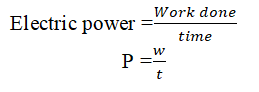
ELECTRIC POWER
Electric power can be defined as the amount of electrical energy consumed per second in an electric circuit. The SI unit of power is Watt(W)
If w be the amount of electrical energy consumed in t seconds then,